Wednesday, 16 July 2014

Holes In Walls...and Powerline 48s

All,

Holes In Walls.


Well the modelling room is now totally complete and ready to be "lived in".  Maybe the term "totally complete" is a bit of a misnomer where anything model railways is concerned but I now have a well laid out room that is away from the layout room and away from the house.  Over the next couple of weeks I will populate the room and sort out the storage issues and creature comforts in this man-cave within a man-cave.

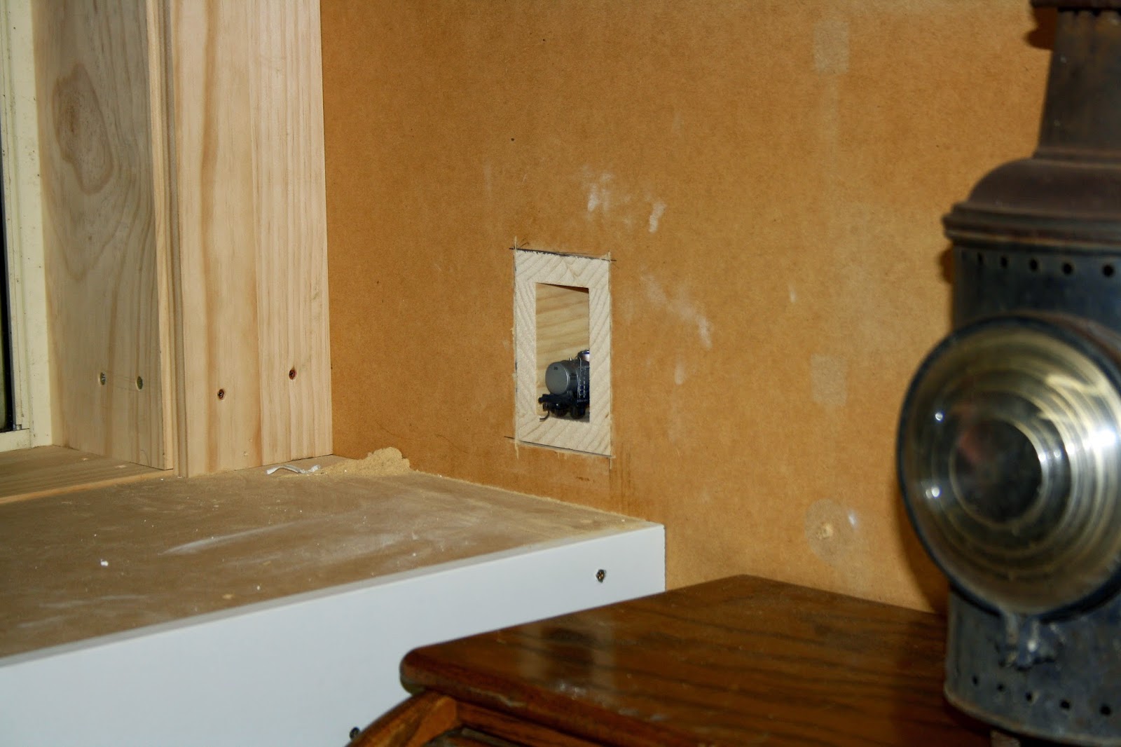
I have however progressed the railway access to this room and have completed the "tunnel" which is essentially a hole in the wall.  The initial trackwork in this room, will consist of a master siding with run around or loco escape and a dead end siding.  I do have to admit that the bench height in the modelling room should have had a bit more thought put into it. I was governed by the window sill height in this room...but now with the rail extension entering this room at layout room level...I have only around 55mm+/- between rail level and the installed benchwork (refer photo) and this will require some thought if Cobalt point motors are to be utilised here.  It may be that I will have to also cut clearance holes in the benchwork to allow clear fitment....ah well it will all become apparent in later posts I guess.


Powerline 48s

 
While awaiting the Trainorama 48 class release...I have relented and purchased a Powerline 48 to add to the fleet and while I have read mixed reviews of this offering...I have decided to convert this example of the mighty 48 class to DCC and Sound and carry out a few more modifications along the way.  As part of this process I thought it might be fun to record the conversion via the blog and of course it will be written in instalments as tasks are completed.
 
I guess a "mini review" of the out of the box model should precede the conversion...so here are my initial thoughts.
 
The model, on first inspection, certainly is impressive and appears to be a more than fair facsimile of these workhorses of the NSW fleet.  I must point out that I was disappointed that there were no written instruction sheets that came with the model. In light of the fact that this is a dual mode model which allows DC operation as well as DCC operation, and the selector switch requires the removal of the body to activate...I find the absence of any written information beyond belief...  What is also obvious is the removable hatch located between the fan and the exhaust stack on the roof of the long end hood... although I am yet to workout what this hatch allows access to???.  Anyway the rest of my "review" will follow as part of the conversion process.
 
This afternoon I decided to undertake the task of removing the body from the chassis and while I had read the varying degrees of success that other modellers have had with what should be a rather easy exercise...I have to state that it was a very trying hour or so as I cajoled the body away from the chassis and as others have suggested...it is a pig of a job.
 
Firstly the two couplers were removed and the four body screws were removed.  On other models this should now allow the body to simply come apart from the chassis...not so here!.  Apart from the tight fit of the two mating parts...there is also the issue of the buffer locating pins that extend inboard thru the pilots, fouling the chassis removal.  The options are either to remove these pins or to bend the pilots outwardly enough to allow the chassis to clear them.
 
The shot above shows the offending buffer guide pins with the chassis now removed
 
 
With the body now removed and an ever growing pile of detail items that have been dislodged during the process...the first thing that becomes apparent is that the "crew" will need to be relieved.  The installed offerings quaintly resemble the green "army men" that I played with as a child and are devoid of any painted features which is magnified by the fact that the loco is modelled with open cab side windows, making these little green blobs even more conspicuous.   I am certain that I have a more suitable replacement crew from the "B" end of a Trainorama loco...
 
The "Army Men" crew...One appears to either be waving...or has just thrown a grenade...
  

The next puzzling feature of this model is the placement of the DC/DCC selector slide switch...which requires the removal of the body to gain access...As stated earlier...I have no idea just what the removable roof hatch is for???.  Someone more learned than me might reveal the true reasoning for it's placement and use and why the selector switch could not have been installed in a more easily accessible location... For me the issue will not prove to be a long term negative as most of the existing electrical internals will be discarded when the DCC / Sound conversion is completed 
 
The main circuit board of the loco...in the background the access hatch on the roof of the long end hood has been removed...
while the location of the DC/DCC selector switch can be discerned at lower left of the circuit board... 
The dislodged parts scoreboard so far....of course impatience and aging fingers have played a part...!!!
In the next instalment...the DCCSound conversion kit should have arrived and I will move on to stripping the loco for decoder and speaker fitment, wiring mods...In the meantime I will scour the web for info from the "trailblazers" of this particular conversion...

Tuesday, 1 July 2014

Almost Ready To Load...

All,

Well another project is nearing completion.  The Captains Flat ore loader has now been given a home and the mini diorama is all but finished.  I say "almost complete" but of course as we all know, there are always details to be added and to magnify that point, the issues are certainly highlighted when you point a camera at the subject and have photos that clearly show the known deficiencies, but... they also tend to show up the unknown as well.  The camera never lies.... is certainly an apt saying in our hobby.

While I am happy with the overall "feel" of the diorama there are some things that I am finding hard to reconcile in my mind.  The most obvious is just how barren the surrounding landscape is.  This certainly mirrors the actual prototype location in latter years...but it seems even more stark when modelling such a small portion of the area.  The ore and the mining operation has rendered the soil almost sterile and as I think I have stated in an earlier post, the lack of any real vegetation is still evident today some 50 odd years since mining activity ceased.  I guess that is why the actual structure and the rail infrastructure needs to be as accurately reproduced  (as my skills will allow) as there is not much else to share centre stage in this project.

To recap...the actual loader is manufactured from laser etched and cut basswood.  The cladding is proprietary corrugated card.  The rails are code 75 nickel silver ( ex flex track ) with copper clad sleepers placed at regular intervals to maintain correct gauge.  The rails are pre weathered before laying. To "hand lay" track I follow the above method and then run a bead of contact adhesive along the bottom of each rail and leave it to go tacky.  I then position the track over pre-laid, ballasted and weathered basswood sleepers and then run along each rail head with a hot soldering iron which tends to remelt the glue and allow adhesion to the sleepers. I am not sure where or when I came across this method and I am not even sure whether it is a popular method to hand lay track...but I find that it gives a brilliant bond.  The other item that needed to be custom manufactured was the wagon weighbridge platform and I was able to portray these items utilising laser cut styrene with an etched pattern to simulate the cast deck and details.  

The scenery is the foam underlay covered in plaster bandage method with an earth coloured plaster slurry over the substrate.  I have then added sieved earth dust collected from adjacent to the "real" Captains Flat loader.  To tie it all together I utilise a neutral set of colours and with the aid of an airbrush, set about highlighting the various shades and shadows that are apparent in the prototype scenery....(well I try anyway).  The grass is just common or garden static grass with added "tufts" in various shapes and lengths.

So...what next?....The road to the loader ramp needs to be completed.  A couple of modified dump trucks will be added as well as a number of minor detail items such as a 44 gallon drum next to the weighbridge deck and a few pieces of  scrap timber and the like. I have yet to add the communication tube and chimney to the weighbridge office.  The one detail item I still need to research is the actual ore.  While my research material shows many black and white photographs of the loader in use...they do not adequately spell out the appearance and more importantly the colour of the ore/slurry mix.  I have a few photos of the mined ore and have added one of these photos to illustrate this post but I am not sure whether this is an adequate sample to prompt a decision.  I have made some calls to locals from the area and hopefully something will turn up.  I feel that is important to get this aspect right as the ore would have littered the area around the loader and would form the basis for any S truck loads to be completed...

And so with this project approaching completion...my mind is wondering what to attack next???


Friday, 27 June 2014

Nearly Time To Move In!!!

All,

Well this weekend should see the completion of the long awaited modelling room.  Windows to be cleaned, 4 gang power point to be fitted and if I am lucky the girls might organise a cake or some other fat inducing treats to mark the occasion. I can't see a full blown house warming party anytime soon...so a piece of cake and a cuppa will suffice.  I should also add that the wood rack will also be relocated to the main shed and my trusty old roll-top, station masters desk will come out of storage and sit in it's place.

There has been a bit of rethinking, with the original room plan incorporating the airbrush cabinet and extraction system.  This will now be sited ( along with a paint cabinet ) in a yet to be completed setup out in the main part of the shed.  It will be great to finally be able to setup the solder stations, another computer for decoder programming, TV, radio and other tools and machinery in a permanent location that can be left at the end of a modelling session without the need to completely reconfigure the room which is what I have to do now when modelling inside the house.  I also have a fair quantity of railway plates, lamps, castings and memorabilia that will now find a home and who knows...in the next few weeks I may just install the upper quadrant signal and lamps outside the shed to finally establish that the shed is indeed a fully fledged rail nut paradise!

The attached shots show the shed almost inhabitable with the benches and all lining complete, floating floor installed and surface mounted power now available on both sides of the shed.  I decided to run the 240V power in conduit well away from the bench tops as I did not want any issues when the layout power bus is brought into the room with the arrival of the repair road branch.  It may interest some that the cabling that can be seen coming through the wall in at least one of the shots was once the power supply for the outdoor "Gauge 1" empire that once circumnavigated the backyard...I have left all power in situ for the possibility that one day it may be resurrected...cannot see this happening anytime soon, but as all cabling was laid in a tidy grid pattern housed in buried conduit...it seemed silly to pull it all up.  I will just fit a junction box in the modelling room and terminate the cables neatly.

I have also included a shot that shows just where the "repair branch" will enter the room and once the timber rack is removed...I will have better access to this location and will soon reroute the layout main lines ( as discussed in the last post ) and prepare for the excavation and tunnelling of the wall that divides the layout room with the modelling room.

And so another project is coming to fruition...slowly but surely the shed is becoming the area that I had envisaged it to be all those years ago. Oh and before someone poses the question regarding colour scheme for the modelling room...don't ask...as I hate painting ( models excepted ).  In the interim the room will remain  "a la naturale".

Timber rack to be replaced with the desk and all is in readiness...

Location of the entrance of the "repair branch"

Plenty of wall space for all things "trains"
          

Monday, 16 June 2014

The Modelling Room Branch

All,

With the modelling room finally coming to fruition, the time has arrived when a final path for a branchline to this room has to be decided and implemented.  The reasoning for the provision of this line was originally borne out of the simple fact that the new room adjoined the layout room and would give the opportunity to transfer locos and rollingstock to a dedicated servicing, repair and maintenance area away from the layout without having to handle them unnecessarily. 

Over time is was realised that this room and associated terminus, would also facilitate a need for an "as required" transfer movement where during normal running sessions...any piece of faulty rollingstock could be placed on a chosen "repair" road at Fish River yard and then when decided a special train would transfer this stock to the modelling room.  Indeed it may well end up that a mainstream terminus with station and yard may morph into being and in time this transfer branch may end up being a revenue style destination requiring a variety of passenger, freight and mixed style trains.  In the meantime I have been examining the best way of  branching off already laid track to give access to the modelling room.

To understand the issue at hand, I guess that a little history is warranted so that the casual reader can follow my logic a little better.  Fish River was always planned to be the centrepiece of the layout and was to be a medium size station and yard, situated between two major centres and serviced by a double track mainline. Over time I made the decision to trim back my planned "empire" and reduce the layout to a single mainline. With this decision made, I decided to leave the already laid "up main" in place and utilise it as a passing loop with the up extension between the branchline junction, across the Fish River bridge and as far as the double track tunnel portal, as a shunting neck.  I guess the prototype equivalent for this main line rationalisation would be sections of the Main Western line in NSW.   In the down direction from Fish River the main and loop revert into a single line as they leave town.

My idea was for the previously described shunting neck to be extended...but because it needs to cross the main line to get to the modelling room... grade separation was a possibility to cross the main and then enter the modelling room.  The problem with this plan was that the bench height in the modelling room is governed by the window sill height in that room and if the line entered this room under this plan,  it would be around 180mm higher than the bench height and would also severely impede one window...not really workable.   So the most recent plan is for a diamond crossing to be installed just beyond the tunnel mouth ( in the hidden siding room) and for the two tracks to now be transposed in orientation and entry to the modelling room should now only be around 50mm above bench height...certainly not the most conventional method of overcoming the problem...but it certainly avoids track sharing via points etc and does not require any grade separation.  It must also be stated that all of these modifications are unseen and occur in an "off layout" area.

The chosen method will also have an added bonus of exposing me to a diamond crossing as I have never utilised this type of unit...and I have also chosen a Tam Valley, Frog Juicer to look after the frog polarity issues...so this will be an opportunity to learn some new aspects of the hobby.

I have included some diagrams of the layout so as to aid the reader... 

Overall diagram of the layout with the required branch to the modelling room between "X" , "X"
The other track between points "I" and "G" is an existing branchline that will be visible but separated from the main line
and modelling room branch via a scenery divider...the main line will re-enter view at point "F" through a tunnel portal and cutting before crossing the doorway on a removeable section. 


The chosen method of trackwork modification...The diamond crossing at point "A" and the mods required to reorient the tracks at point "B"
As can be seen this will relocate the modelling room branch to the outside of the main line and facilitate it for entry to the modelling room which is located through a wall to the right of the layout room.


Saturday, 14 June 2014

Captain's Flat....Progress At Last

All,

With the modelling room now well on it's way towards completion, a change of pace was required and I took some time to move ahead with the Captain's Flat ore loader.  I have decided to build the structure into a mini diorama so that if it does not end up as an inclusion on the layout it will at least have a home that can be added to the "shelf" pieces I have already built.  I say "if" included for good reason as the only logical place for it and associated sidings on the layout would be on the as yet uncompleted section of the layout which is directly opposite Fish River yard.

So with the diorama carcass built, it was time to research and construct the weighman's hut which on the prototype, was located directly under the loader shed and adjacent to the track. With this quaint...but rudimentary little shed basically completed, the whole structure can be placed onto the diorama so that final scenery contours can be worked out.

As I studied the prototype photos for the gazzilionth time...it is not difficult to be drawn into imagining what it must have been like to have worked in this relatively harsh environment.  I guess the weighman would have had other duties as I can't imagine that this job would have been a day to day "whole of shift" proposition. As there was no stockpiling of ore at the loader, the job obviously depended on when wagons were available to load and the frequency of trains.  I have no idea if there was any "manual" movement of wagons...so there certainly would have been down time at this location.  Perhaps the weighman was also engaged in work associated with the goods shed that was opposite and adjacent to the loader.  Or he may well have been purloined from the actual mine when and as required.  At the end of the day it would have been a fairly dirty, dusty, noisy and unpleasant job as the ore free fell from the trucks above, through the chute and into the S and K trucks within almost arms length from his workstation.  Winters would have been uncomfortable and summers would have been almost unbearable with the ever present danger of snakes and other vermin having almost free access to the poorly insulated and sealed "office".   I have learnt that there was a fuel stove in the shed and also a communication tube between the shed and the loader above, which allowed communications between the truck driver and weighman.  Apart from the items spoken of here and of course the actual weighscale...it would appear that creature comforts were minimal and it certainly was a spartan existence.  I have also come across some period photos that show there were raised platforms either side of the loader and adjacent to the outer rail that I imagine were used for "trimming" the loads and I guess this would have entailed extra workers at peak times.  I am not sure whether I will include these platforms in the actual model...but I guess for fidelity sake I should research them further as they would certainly add visual interest to the scene.

The scenery will be a fairly easy and plain operation as one thing that was still obvious up until a few years ago is that the ore slurry and tailings that had built up in the soil over many years, certainly curtailed any plant growth near the rail corridor.  Indeed it took over 40 years for any real recovery of the plant life within the corridor of the bulk of the branch to gain any obvious foothold.

I have also been fortunate to have found some road trucks that match the type used on the prototype, amongst my large collection of "stuff" and I will certainly convert at least two of them once the final detailing takes place.  As can be seen in the attached photos, I have also decided to include two sidings on the diorama and while one will be the actual loader road, I will try and include a yard crane straddling the other siding.  There was one located on the prototype just beyond the loader and adjacent to the goods shed and it's inclusion on the diorama will add scenic value I feel.  One other feature will be the inclusion of the actual weighbridge decking and this will be constructed from laser etched and cut engraving plastic with the casting patterns and detail included.


Sunday, 8 June 2014

Modelling Room Progress

All,

Well the Queen's Birthday long weekend is upon us and around 30 to 40 years ago this particular weekend rivalled Christmas for any kid (or budding pyromaniac) due to the Saturday night meaning Cracker Night.  Bonfires were constructed and any spare change was spirited away to augment the large bag of fireworks that were supplied by my ever suffering parents.  But of course...like most things that that have any sniff of fun attached to them, the bureaucrats snuffed that  "kid's right of passage" many years ago.

Of course these days,  fun to me is a couple of days devoted to the hobby and as the "planets aligned" with no other commitments for the long weekend, it was purely a decision of which aspect I would engage in.  In the end, the long dormant progress on the modelling room won out.  To those unfamiliar with the earlier postings surrounding the layout of the shed that houses "the hobby", a brief description is in order so as the casual reader will be able to follow this post.

The shed in question is 12 metres long x around 7 metres wide. A lined layout room takes up a 12 metre x 4 metre section of the shed and this area is in itself divided into 2 rooms due to an earlier wall that existed before the shed hosted a layout...the main layout room is 9 metres x 4 metres and on the end of that is another room 3 metres x 4 metres and access between the two rooms is via a doorway.  The original plan was that to have a 9x4 metre layout room with the 3x4 metre portion being a staging area...but of course regular readers would be aware that this plan has been modified.

I decided some time ago to add a modelling room and set about lining another area of the main shed adjacent to the layout room.  This area works out at 3 metres x 3 metres and has two good size windows for natural light and faces north so it is an ideal location.  The method of lining has been carried over from the original construction with timber frame, walls and roof insulated and MDF utilised as internal cladding.  This will be the 4th winter that the layout room has been in existence and the lining methodology has proved itself by maintaining a relatively even temperature right throughout the year.  For those unfamiliar of the climate here...summers can yield 40 degree C days and winter can regularly offer minus temperatures with sleet and snow a possibility.  Indeed this morning's minimum was minus 4.5.  I have left provision for a "pot belly" type combustion heater...but would doubt it will ever be fitted due to the required heat up time and the irregular use of the room.  One other aspect is that the ceiling of the layout room also has a yellow tongue type flooring fitted above the rafters to offer mezzanine type storage and also sandwich the ceiling adding another layer of insulation.

The modelling room, when complete, will offer a place away from the layout to carry out maintenance work, infrastructure and kit building and just a place to "chill out".  Storage of tools, equipment and all things "layout" will also find a home.  I have stated before that it is likely that a "repair" road will be laid in to the room so that wagons can be transferred for work required...or a branchline terminus may also eventuate...who knows?

Anyway as can be seen in the attached shots...all lining has been completed with window framing almost complete. One bench has been built and provision for another in place.  Timber trims will be installed around the windows and at all lining joints and I also have a fair amount of brand new floating floor packs that were destined for a long ago house job that are no longer required after those renovations and This will be added to take the edge off the concrete floor.  To complete things is provision for a ceiling trapdoor to give an additional access the ceiling storage.

It will be nice to get this job finished over the next few weeks as it will then allow for the remainder of the main shed to be sorted, cleaned out and tidied up.


The layout room wall is to the right of shot...with the access door for the layout room...behind and to the right of the photographer...


Friday, 30 May 2014

Burke's Backyard and The Layout...

All,

I think it was Don Burke who originally advocated placing newly purchased pot plants around a garden to ensure correct placement before actually planting...  I guess we in this hobby have been following that adage for many years before he ever appeared as the "garden gnome" on TV.  In the case of model railroading it is not only trees and shrubs...but also track, structures, scenery and most other items that are positioned around a layout to ensure that "it all fits" from an aesthetic and operational point of view.

As touched on in an earlier post, I have been working on the location of the Argyle Flour Mill and just when I thought I had it all worked out...doubt has crept in regarding the ultimate positioning of this industry.  It is not so much the flour mill in isolation...but more about how the placement will affect the overall "look" of this location.  I have included some photos of the trial fitment of the mill and they should allow the reader to follow my logic.  I must firstly explain that the mill will either be just the solitary building or, as also shown, with a silo complex / grain unloading shed, most likely a boiler house and one or two small outbuildings. 

       
So here is the view including the solitary flour mill building...and to my eyes, even though the area has not been fully scenicked... the placement just looks too big and bold and tends to make the bridges appear to be out of scale or lacking in bulk or height. It could also be the fact that the mill is on a slightly elevated track and would have been better suited to have been in a hollow slightly hidden with landscaping or conversely the main lines may well have been better placed on a rising grade with the bridges approached via embankments...anyway, we are too far down the track for that modification to be retrofitted!  


Another shot showing the yet to be modified silo and grain unloading shed added The silo complex will need some work as it is presently depicting a structure for the cement industry and ultimately (if utilised here) will need the roof structures removed and a conveyer shed added and an auger chute to transfer grain to the mill.  Again the industry seems to overshadow the rest of the scene.   As I write, my wife has just poked her head over my shoulder to view the photographs and she also suggested that the scene looks "too congested" and maybe that is another aspect that comes into play.

I guess I will just have to play with other suitable industries over the weekend and maybe try a "lighter feel" like a petroleum depot and attempt to hide or tone down the industry with landscaping.  In the end it would be a shame to deviate from the original flour mill plan.  Ah well...tomorrow is another day!

On a more positive note, I received a fairly large and much anticipated, combined shipment from the US this morning from a number of suppliers.  With regards to one supplier called Scenic Express, I tend to place an order about twice a year with them and apart from a heft amount of static grass and other sundry items, I ordered some ready made weeping willows to place along the river bank.  I have planted a small amount already and feel that they have certainly improve the somewhat naked look that this area once had.  Based on my initial reaction and the reduced prices...I will be ordering a lot more differing types of trees made by this particular manufacturer to augment the home made varieties already growing on the layout....Don Burke would be proud!