Monday 28 July 2014

Off On Another Tangent

All,

Well, the 48 class is now completely stripped, the DCCSound decoder and speaker kit has arrived and I have purchased the required resistors to complete the lighting circuits when the rebuild begins.  I have been keeping careful records and photos for the next instalment in this conversion...But the subject of this post is about as far removed from loco rebuilding as one can be.

I had better begin this post by describing a fellow blogger.  Iain Robinson maintains a blog called (strangely enough) Iain Robinson Modelmaking  and he may well be familiar to some of you.  I happened across this site a couple of years ago and have been hooked ever since.  While the subject matter of Iain's work is somewhat removed from the Australian scene...the research, methods, craftsmanship, attention to detail and his immersive writing style and photography of the projects are certainly awe inspiring to say the least.  Iain is certainly a "master modeller" in the true sense of the word...I guess an artisan would aptly describe him.  Now, while I would never in my wildest dreams ever attain the level of skill that he makes look all so easy...there is plenty of hints, tips and inspiration to be gained from a visit to his blog and because of this I have embarked on my latest project ( yep...one of many in the process of completion stakes).

As much as I have built a number of structures over the years for pleasure and for the layout and have utilised a number of mediums to do so...I guess I have settled into a routine and have unconsciously fallen into a pattern of staying well and truly within my comfort zone.  To this end I have made a conscious decision to try a medium that has attracted my interest for some time...but for one reason or another has never made it to the top of the deck.

Iain utilises DAS modelling clay in some form or another in most of his structures and I decided to "start at the start" and see where this material would take my imagination and assess whether I could adapt it into my modelling "habits".  I have for some time had a desire to explore and build a besser block and corrugated asbestos composite industrial type building...examples of which dotted the "pre enlightened" industrial landscape.  In the Botany area of Sydney...where I grew up,  there were a multitude of these buildings and the design seemed to be a standard.  Concrete floor with besser block "brick up" to a level of say 8 to 10 courses and then corrugated asbestos sheet continuing on to the roof line....all of this cladding normally wrapping around a steel skeleton of RSJ / I beams. and the pitched or sawtooth roof followed the theme of corrugated asbestos as well.

Unfortunately I never pointed a camera at this type of building and as much as I recall the general appearance...I needed a reference photo(s) and certainly a building that was local to my childhood area and familiar would be a plus.  I recalled a shot that I had seen many years ago and I was able to uncover it in the publication called Remember When II and I have included it here...( Photo Credit... to Ted Skiller and the ARHS )


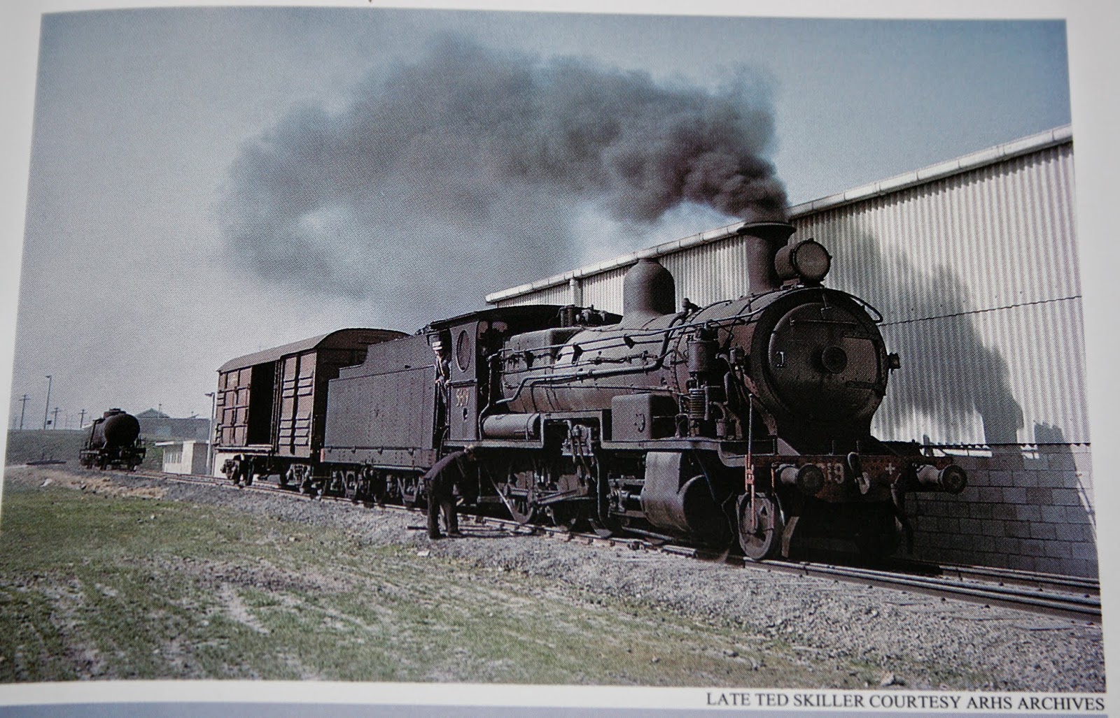
   The shot was taken inside what was once the ICI Botany site and as much as it shows only a glimpse of what I would like to recreate...the important elements are there and imagination will take over from here...

In the case of the corrugated asbestos...I ordered around 40 sheets of the OO scale plastic offering from Wills ( UK) a couple of years ago and as is normal with most model related purchases...I knew I would find a need for it...someday.   While I am aware that it is slightly over scale it does possess the flavour I am looking for and it is convenient.  On the down side it is way too thick and is only single sided so this will have to be taken into account as well.   


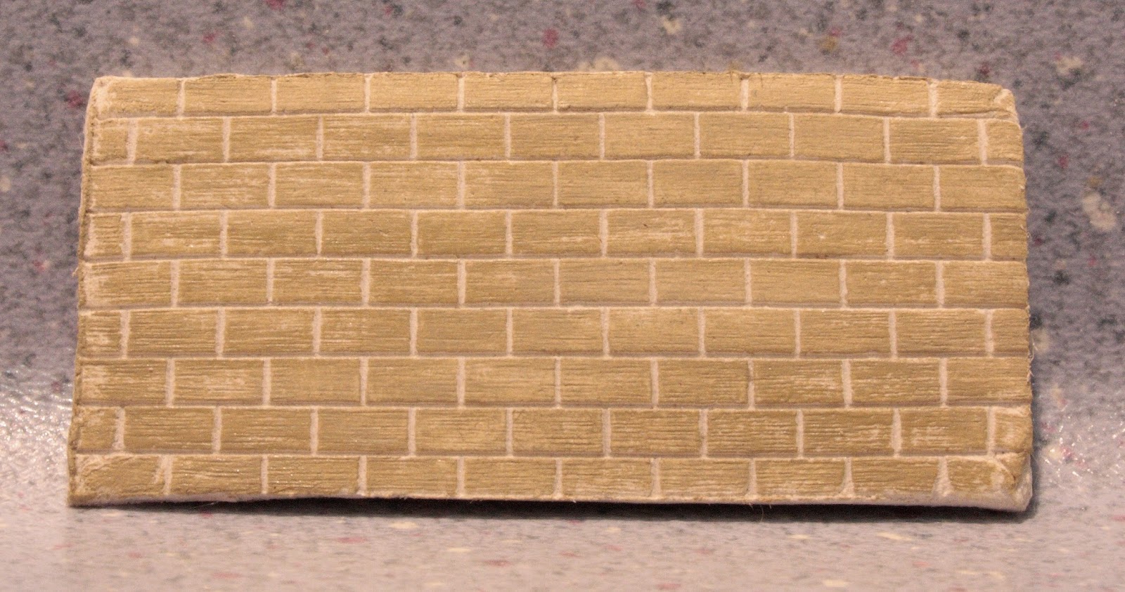
And now we finally get to the trial and error part of this essay and that is the creation of the besser blocks   I purchased four 1kg blocks of DAS modelling clay last Christmas and "donated" two of these blocks as stocking fillers for my daughter and kept the other two on hand awaiting an opportunity to "play" with the stuff and discover the uses for our hobby.  With the dimensions of besser blocks now entered and scaled to HO, I attempted to laser etch a set of templates or probably better described as stamps from engraving plastic... to allow "panels" of besser blocks to be easily formed.  The initial results are encouraging and I now need to tone down the mortar joints, as these were not normally raked as deeply as I have portrayed and I think I will use cast acrylic for the next set of stamps as this material has less flex and should produce a more consistent indentation.  (On a positive note, I am happy with the surface texture I have been able to achieve).  I will also attempt to create moulds as well so that uniform thickness of the panels can be maintained and double sided mortar joints are able to be introduced.  My first impression of DAS modelling clay is that I can see a multitude of uses and the discovery phase will be a fun process.

I have included a shot of a trial panel of besser blocks...  In hindsight I think purchasing four 1kg blocks of DAS modelling clay was very much a case of overkill...


Wednesday 16 July 2014

Holes In Walls...and Powerline 48s

All,

Holes In Walls.


Well the modelling room is now totally complete and ready to be "lived in".  Maybe the term "totally complete" is a bit of a misnomer where anything model railways is concerned but I now have a well laid out room that is away from the layout room and away from the house.  Over the next couple of weeks I will populate the room and sort out the storage issues and creature comforts in this man-cave within a man-cave.

I have however progressed the railway access to this room and have completed the "tunnel" which is essentially a hole in the wall.  The initial trackwork in this room, will consist of a master siding with run around or loco escape and a dead end siding.  I do have to admit that the bench height in the modelling room should have had a bit more thought put into it. I was governed by the window sill height in this room...but now with the rail extension entering this room at layout room level...I have only around 55mm+/- between rail level and the installed benchwork (refer photo) and this will require some thought if Cobalt point motors are to be utilised here.  It may be that I will have to also cut clearance holes in the benchwork to allow clear fitment....ah well it will all become apparent in later posts I guess.


Powerline 48s

 
While awaiting the Trainorama 48 class release...I have relented and purchased a Powerline 48 to add to the fleet and while I have read mixed reviews of this offering...I have decided to convert this example of the mighty 48 class to DCC and Sound and carry out a few more modifications along the way.  As part of this process I thought it might be fun to record the conversion via the blog and of course it will be written in instalments as tasks are completed.
 
I guess a "mini review" of the out of the box model should precede the conversion...so here are my initial thoughts.
 
The model, on first inspection, certainly is impressive and appears to be a more than fair facsimile of these workhorses of the NSW fleet.  I must point out that I was disappointed that there were no written instruction sheets that came with the model. In light of the fact that this is a dual mode model which allows DC operation as well as DCC operation, and the selector switch requires the removal of the body to activate...I find the absence of any written information beyond belief...  What is also obvious is the removable hatch located between the fan and the exhaust stack on the roof of the long end hood... although I am yet to workout what this hatch allows access to???.  Anyway the rest of my "review" will follow as part of the conversion process.
 
This afternoon I decided to undertake the task of removing the body from the chassis and while I had read the varying degrees of success that other modellers have had with what should be a rather easy exercise...I have to state that it was a very trying hour or so as I cajoled the body away from the chassis and as others have suggested...it is a pig of a job.
 
Firstly the two couplers were removed and the four body screws were removed.  On other models this should now allow the body to simply come apart from the chassis...not so here!.  Apart from the tight fit of the two mating parts...there is also the issue of the buffer locating pins that extend inboard thru the pilots, fouling the chassis removal.  The options are either to remove these pins or to bend the pilots outwardly enough to allow the chassis to clear them.
 
The shot above shows the offending buffer guide pins with the chassis now removed
 
 
With the body now removed and an ever growing pile of detail items that have been dislodged during the process...the first thing that becomes apparent is that the "crew" will need to be relieved.  The installed offerings quaintly resemble the green "army men" that I played with as a child and are devoid of any painted features which is magnified by the fact that the loco is modelled with open cab side windows, making these little green blobs even more conspicuous.   I am certain that I have a more suitable replacement crew from the "B" end of a Trainorama loco...
 
The "Army Men" crew...One appears to either be waving...or has just thrown a grenade...
  

The next puzzling feature of this model is the placement of the DC/DCC selector slide switch...which requires the removal of the body to gain access...As stated earlier...I have no idea just what the removable roof hatch is for???.  Someone more learned than me might reveal the true reasoning for it's placement and use and why the selector switch could not have been installed in a more easily accessible location... For me the issue will not prove to be a long term negative as most of the existing electrical internals will be discarded when the DCC / Sound conversion is completed 
 
The main circuit board of the loco...in the background the access hatch on the roof of the long end hood has been removed...
while the location of the DC/DCC selector switch can be discerned at lower left of the circuit board... 
The dislodged parts scoreboard so far....of course impatience and aging fingers have played a part...!!!
In the next instalment...the DCCSound conversion kit should have arrived and I will move on to stripping the loco for decoder and speaker fitment, wiring mods...In the meantime I will scour the web for info from the "trailblazers" of this particular conversion...

Tuesday 1 July 2014

Almost Ready To Load...

All,

Well another project is nearing completion.  The Captains Flat ore loader has now been given a home and the mini diorama is all but finished.  I say "almost complete" but of course as we all know, there are always details to be added and to magnify that point, the issues are certainly highlighted when you point a camera at the subject and have photos that clearly show the known deficiencies, but... they also tend to show up the unknown as well.  The camera never lies.... is certainly an apt saying in our hobby.

While I am happy with the overall "feel" of the diorama there are some things that I am finding hard to reconcile in my mind.  The most obvious is just how barren the surrounding landscape is.  This certainly mirrors the actual prototype location in latter years...but it seems even more stark when modelling such a small portion of the area.  The ore and the mining operation has rendered the soil almost sterile and as I think I have stated in an earlier post, the lack of any real vegetation is still evident today some 50 odd years since mining activity ceased.  I guess that is why the actual structure and the rail infrastructure needs to be as accurately reproduced  (as my skills will allow) as there is not much else to share centre stage in this project.

To recap...the actual loader is manufactured from laser etched and cut basswood.  The cladding is proprietary corrugated card.  The rails are code 75 nickel silver ( ex flex track ) with copper clad sleepers placed at regular intervals to maintain correct gauge.  The rails are pre weathered before laying. To "hand lay" track I follow the above method and then run a bead of contact adhesive along the bottom of each rail and leave it to go tacky.  I then position the track over pre-laid, ballasted and weathered basswood sleepers and then run along each rail head with a hot soldering iron which tends to remelt the glue and allow adhesion to the sleepers. I am not sure where or when I came across this method and I am not even sure whether it is a popular method to hand lay track...but I find that it gives a brilliant bond.  The other item that needed to be custom manufactured was the wagon weighbridge platform and I was able to portray these items utilising laser cut styrene with an etched pattern to simulate the cast deck and details.  

The scenery is the foam underlay covered in plaster bandage method with an earth coloured plaster slurry over the substrate.  I have then added sieved earth dust collected from adjacent to the "real" Captains Flat loader.  To tie it all together I utilise a neutral set of colours and with the aid of an airbrush, set about highlighting the various shades and shadows that are apparent in the prototype scenery....(well I try anyway).  The grass is just common or garden static grass with added "tufts" in various shapes and lengths.

So...what next?....The road to the loader ramp needs to be completed.  A couple of modified dump trucks will be added as well as a number of minor detail items such as a 44 gallon drum next to the weighbridge deck and a few pieces of  scrap timber and the like. I have yet to add the communication tube and chimney to the weighbridge office.  The one detail item I still need to research is the actual ore.  While my research material shows many black and white photographs of the loader in use...they do not adequately spell out the appearance and more importantly the colour of the ore/slurry mix.  I have a few photos of the mined ore and have added one of these photos to illustrate this post but I am not sure whether this is an adequate sample to prompt a decision.  I have made some calls to locals from the area and hopefully something will turn up.  I feel that is important to get this aspect right as the ore would have littered the area around the loader and would form the basis for any S truck loads to be completed...

And so with this project approaching completion...my mind is wondering what to attack next???