All,
One certain piece of infrastructure that will find a spot on the layout will be a Cream Shed. Regular readers of this blog will be aware that I have a soft spot for these often overlooked little lineside gems and with the long weekend upon us the time was right to build a cameo scene type mini module that may one day grace the layout.
From my research it would appear that most cream sheds were either a free standing unit with a trackside platform ramped at one or both ends and the whole structure was raised to track level with traditional piers etc....or were positioned on a station platform with the rear of the shed cantilevered on timber or brick piers. In this case I have decided to utilise a design that I have only ever seen used in one prototype location and this incorporates an earthen type loading bank configuration with timber facing and the shed fitted as per a station platform type arrangement.
As it happens we have the facing kit...so the opportunity was taken during the week to at least make a start on the major components and give myself a head start for the weekend. It would appear that the majority of cream sheds were painted white ( white washed ) when new and as the layout period will span the transition years, I figured that most sheds that still existed at this time would be lacking in maintenance as they fell out of favour as a useable commodity. In keeping with this logic I have attempted to model a shed that still shows a hint of the paint scheme of the past but in serious need of some TLC which as history has shown was never bestowed on them and in most cases they were unceremoniously demolished as the newer regime of milk product handling took over.
Anyway I have included a couple of shots of progress thus far and I look forward to the weekend as I attempt to bring the scene to life, as best I can. The shed itself will have the underfloor detail and weathering added as the scene takes shape and the facing has been partially pre-weathered and awaits burial into the scene.
Hopefully ( if I can stay under the domestic radar ) I will post some more progress over the weekend.
Saturday, 8 June 2013
Sunday, 26 May 2013
More Musings and Paintless Weathering
All,
The trouble with posting frequently is that when you don't post for a week or so the rumours start to grow and the questions start to flow. So... no i have not moved into the retirement village behind where I live and the "hospice" rumour is starting to wear thin....But i do get a laugh so all is good.
Our hobby appears to be going through some changes and also a major shift away from the basics of what used to be the cornerstone of layout building and that is "Scratch Building". It is now about 40 odd years ago that i first got started in this great hobby and the desire to have something more than a Triang or Hornby piece of rollingstock or lineside item back then, meant a certain commitment to stretch one's faith in yourself to have a go at buiding your own. The desire to recreate the local and familiar Aussie prototype in model form meant purchasing available scratch building materials, some rudimentary tools ( sometimes to include raiding Dad's highly treasured tools ) and go about creating the landscape for your trains to run through, the lineside detail items and of course the locos and rollingstock as well.
Of course at that time the first or second generation of locally produced rollingstock kits were hitting the market and while they were extremely crude by today's standards, they were certainly well recieved and were a leg up to speeding the layout creation along. Even though they were "kits" in the strict sense of the word...even these mouth watering offerings created by local visionaries still required a good level of dexterity and skill to end up with a reasonable facsimile of the intended wagon or loco.
Roll the clock forward 40 years and we are now absolutely spoilt ( although our credit card account would think differently ) by the ever increasing quality of ready to run locos, rollingstock and ready to place lineside items...most approaching museum quality. So....what is wrong with that? ...every facet of our lives is going through the same types of changes that are invented and marketted to enhance our quality of life. I cannot argue with these facts and of course have heavily invested in a fair quantity of the recent offerings....But i can't help but wonder the slow demise of what used to be the "trainer wheels" of the hobby and that is "Scratch Building"
I personally offer that the hobby may experience a renaissance where because of the high level of quality RTR locos, rollingstock and ready made structures, people may well find that they have more time to focus on the landscape in which their museum pieces travel or like me strive to create a higher level of realism in these areas where possible. For me this is through weathering of rollingstock and always trying to raise the bar and attempting to achieve a better level of lineside structure quality and realism.
While i am penning this post, the fact not lost on me ( and many blog followers would be aware ) is that I am fortunate to have the machinery at my disposal that does take a lot of the menial and repetitious tasks away and does make my chosen tasks a lot easier. In the end though...if one is to create anything we still need to be able to imagine, visualise and research the intended creation....Something that scratch building ( luckily ) instilled on me many years ago...
With the "Musings" part of the post out of the way it is time to move onto something that some blog followers may find interesting...
As alluded to in an earlier post...I have been experimenting more and more with the available options for weathering timber structures. Part of this is the ability to weather and age the timber without the need for paint. While i have nothing against paint personally... I just think that there are more suitable mediums to achieve the outcome I am after and that is to compliment the raw material and not mask it. With the added attraction being the fact that there is nothing i like more than varying my approaches to the hobby. While the following photos are of a well worn ( on this blog anyway ) subject...I think the latest incarnation certainly shows subtle differences in the approach and result of trying these different mediums. I have still utilised my well worn approach of giving the timber a first coat of the Raven Oil mix...but have then used my "new friends"....the pastels. I think i am nearly there with this approach and am gaining more and more confidence as each new structure rolls off the assembly line.
While talking about the bridges and seemingly flying in the face of my earlier musings portion of the post...we are, because of demand, taking orders for those in the hobby who would like a single or double track span bridge built, weathered and ready to "plonk"....If this interests you...just drop us a line and we will discuss your requirements.
In a future post I will also touch on the use of round piles for the bridges and what this means for our upcoming trestle and timber opening range....
The trouble with posting frequently is that when you don't post for a week or so the rumours start to grow and the questions start to flow. So... no i have not moved into the retirement village behind where I live and the "hospice" rumour is starting to wear thin....But i do get a laugh so all is good.
Our hobby appears to be going through some changes and also a major shift away from the basics of what used to be the cornerstone of layout building and that is "Scratch Building". It is now about 40 odd years ago that i first got started in this great hobby and the desire to have something more than a Triang or Hornby piece of rollingstock or lineside item back then, meant a certain commitment to stretch one's faith in yourself to have a go at buiding your own. The desire to recreate the local and familiar Aussie prototype in model form meant purchasing available scratch building materials, some rudimentary tools ( sometimes to include raiding Dad's highly treasured tools ) and go about creating the landscape for your trains to run through, the lineside detail items and of course the locos and rollingstock as well.
Of course at that time the first or second generation of locally produced rollingstock kits were hitting the market and while they were extremely crude by today's standards, they were certainly well recieved and were a leg up to speeding the layout creation along. Even though they were "kits" in the strict sense of the word...even these mouth watering offerings created by local visionaries still required a good level of dexterity and skill to end up with a reasonable facsimile of the intended wagon or loco.
Roll the clock forward 40 years and we are now absolutely spoilt ( although our credit card account would think differently ) by the ever increasing quality of ready to run locos, rollingstock and ready to place lineside items...most approaching museum quality. So....what is wrong with that? ...every facet of our lives is going through the same types of changes that are invented and marketted to enhance our quality of life. I cannot argue with these facts and of course have heavily invested in a fair quantity of the recent offerings....But i can't help but wonder the slow demise of what used to be the "trainer wheels" of the hobby and that is "Scratch Building"
I personally offer that the hobby may experience a renaissance where because of the high level of quality RTR locos, rollingstock and ready made structures, people may well find that they have more time to focus on the landscape in which their museum pieces travel or like me strive to create a higher level of realism in these areas where possible. For me this is through weathering of rollingstock and always trying to raise the bar and attempting to achieve a better level of lineside structure quality and realism.
While i am penning this post, the fact not lost on me ( and many blog followers would be aware ) is that I am fortunate to have the machinery at my disposal that does take a lot of the menial and repetitious tasks away and does make my chosen tasks a lot easier. In the end though...if one is to create anything we still need to be able to imagine, visualise and research the intended creation....Something that scratch building ( luckily ) instilled on me many years ago...
With the "Musings" part of the post out of the way it is time to move onto something that some blog followers may find interesting...
As alluded to in an earlier post...I have been experimenting more and more with the available options for weathering timber structures. Part of this is the ability to weather and age the timber without the need for paint. While i have nothing against paint personally... I just think that there are more suitable mediums to achieve the outcome I am after and that is to compliment the raw material and not mask it. With the added attraction being the fact that there is nothing i like more than varying my approaches to the hobby. While the following photos are of a well worn ( on this blog anyway ) subject...I think the latest incarnation certainly shows subtle differences in the approach and result of trying these different mediums. I have still utilised my well worn approach of giving the timber a first coat of the Raven Oil mix...but have then used my "new friends"....the pastels. I think i am nearly there with this approach and am gaining more and more confidence as each new structure rolls off the assembly line.
While talking about the bridges and seemingly flying in the face of my earlier musings portion of the post...we are, because of demand, taking orders for those in the hobby who would like a single or double track span bridge built, weathered and ready to "plonk"....If this interests you...just drop us a line and we will discuss your requirements.
In a future post I will also touch on the use of round piles for the bridges and what this means for our upcoming trestle and timber opening range....
Friday, 10 May 2013
Weathering, Pastels and Round Piles...
All,
I have been using pastels for weathering for some time but only to add highlights to models. I read with interest the posting by Ray Pilgrim on his Bylong Blog in January where he utilised another aspect of pastel use for weathering one of our Timber Ash Buffers. As time goes on I am finding more uses and slowly getting use to the characteristics of pastels.
My normal timber weathering technique is to use Raven Oil mixed with methylated spirits to age the timber components ( normally before assembly ) as this gives a good base with which to continue the weathering process....I have covered this in an earlier post I am sure...Then take to the airbrush and dry weathering powders to complete the job. The main concern with timber is the tendency for it to warp should you be over zealous with any form of liquid. This is why i utlise metho if any moisture is required as it is very quick to dry and I cannot overemphasize the need to almost dry brush the timber and take one's time.
During the week I decided to utilise one of the "spare" completed bridge decks to explore the use of pastels further and experiment with differing application methods. They certainly work very well in their dry state....but one idea I explored was to rub the chosen pastel stick on some medium wet and dry to give a coarse powder and then made a very week slurry with metho as the medium and applied with a very fine brush. The effect is certainly different and the method's success can be gauged by the shots below...Some would suggest that the same could be achieved with weathering powders but the variation of shades available in pastels coupled with the cheapness of pastels vs powders makes it an easy choice. While i am a relative novice with pastels...I can certainly see many advantages over weathering powders.
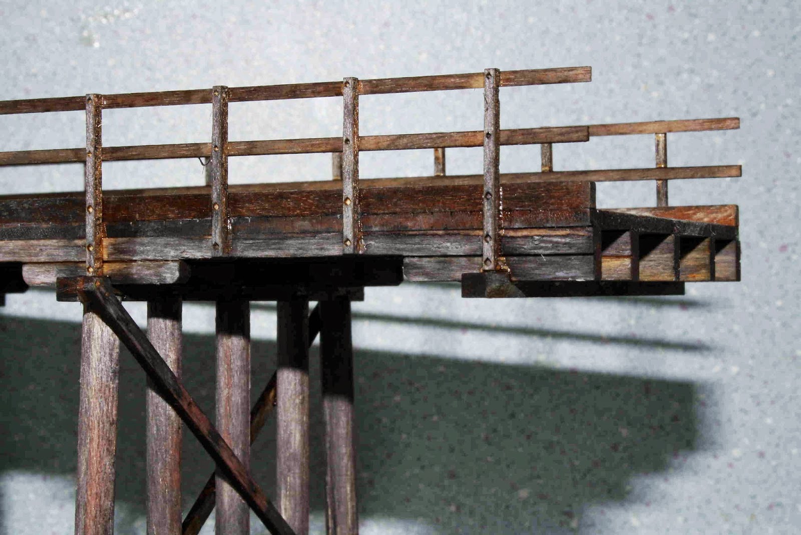
Also during the week ( and following a valid comment re our last post ) I decided to bite the bullet and perfect the manufacture and assembly of round piles for bridge bents. It is certainly an issue that needed to be addressed not only for the bridge range but also for the upcoming Timber Opening range....I have included a shot of the first incarnation in a pre-weathered state.
Enjoy your weekend!!!
I have been using pastels for weathering for some time but only to add highlights to models. I read with interest the posting by Ray Pilgrim on his Bylong Blog in January where he utilised another aspect of pastel use for weathering one of our Timber Ash Buffers. As time goes on I am finding more uses and slowly getting use to the characteristics of pastels.
My normal timber weathering technique is to use Raven Oil mixed with methylated spirits to age the timber components ( normally before assembly ) as this gives a good base with which to continue the weathering process....I have covered this in an earlier post I am sure...Then take to the airbrush and dry weathering powders to complete the job. The main concern with timber is the tendency for it to warp should you be over zealous with any form of liquid. This is why i utlise metho if any moisture is required as it is very quick to dry and I cannot overemphasize the need to almost dry brush the timber and take one's time.
During the week I decided to utilise one of the "spare" completed bridge decks to explore the use of pastels further and experiment with differing application methods. They certainly work very well in their dry state....but one idea I explored was to rub the chosen pastel stick on some medium wet and dry to give a coarse powder and then made a very week slurry with metho as the medium and applied with a very fine brush. The effect is certainly different and the method's success can be gauged by the shots below...Some would suggest that the same could be achieved with weathering powders but the variation of shades available in pastels coupled with the cheapness of pastels vs powders makes it an easy choice. While i am a relative novice with pastels...I can certainly see many advantages over weathering powders.
Also during the week ( and following a valid comment re our last post ) I decided to bite the bullet and perfect the manufacture and assembly of round piles for bridge bents. It is certainly an issue that needed to be addressed not only for the bridge range but also for the upcoming Timber Opening range....I have included a shot of the first incarnation in a pre-weathered state.
Enjoy your weekend!!!
| The bridge deck during the weathering process... |
| Weathering tools of trade...Raven Oil...available from saddlery shops for around $15.00 per bottle...The pastels were purchased via ebay for $12.00 per pack The first round pile bridge assembly... |
Wednesday, 8 May 2013
Compound Girders...Take 2
All,
Following on from the last post regarding the double track span, Timber Road Overbridge.... It was back to the research books and also the drawing board this week. My main concern with the first pilot model was that the bridge girders looked a bit lightweight when compared to the visually pleasing single track version. When searching for photographic evidence of the girder arrangement it dawned upon me the complete lack of historical shots of road overbridges in general...I guess the irony is that most photographers shoot from bridges and not at them...More is the pity!!!
I did though unearth an RTA report or study paper entitled Timber Beam Bridges....A Study of Relative Heritage Significance of RTA Controlled Timber Beam Road Bridges. This 24 page offering is a very interesting read and a font of information on timber beam bridge design...One section also answered the question regarding girders etc
Basically it claims that the standards were....For bridge spans longer than 35 feet ( 11metres ) compound beams were used whereby two 12 inch x 12 inch timbers one above the other would be locked together by a combination of vertical bolts and wooden keys in precut slots across the interface.
By my reckoning...this rule was obviously fairly flexible as i have some records that show shorter spans were compound beams and indeed some longer spans than recommended were not compounded. One would imagine that the road useage or traffic load would also play a part. Another interesting fact was that in some bridges the outer girders were dressed or milled square beams but the inner girders were left in their natural state with bark attached in some instances....all for appearance sake.
Anyway i have concocted another pilot with compound girders "through the span" and have decided to have a bit of fun and dress it up a bit by way of painting and weathering. The weathering is far from complete and the footings need to be converted to faux concrete...but i must admit that the compound girders are easier on my eyes when compared to the previous single girder examples. Nevertheless it would appear that both designs were certainly seen in prototype service and i guess that legitimises the use of both in model form
Following on from the last post regarding the double track span, Timber Road Overbridge.... It was back to the research books and also the drawing board this week. My main concern with the first pilot model was that the bridge girders looked a bit lightweight when compared to the visually pleasing single track version. When searching for photographic evidence of the girder arrangement it dawned upon me the complete lack of historical shots of road overbridges in general...I guess the irony is that most photographers shoot from bridges and not at them...More is the pity!!!
I did though unearth an RTA report or study paper entitled Timber Beam Bridges....A Study of Relative Heritage Significance of RTA Controlled Timber Beam Road Bridges. This 24 page offering is a very interesting read and a font of information on timber beam bridge design...One section also answered the question regarding girders etc
Basically it claims that the standards were....For bridge spans longer than 35 feet ( 11metres ) compound beams were used whereby two 12 inch x 12 inch timbers one above the other would be locked together by a combination of vertical bolts and wooden keys in precut slots across the interface.
By my reckoning...this rule was obviously fairly flexible as i have some records that show shorter spans were compound beams and indeed some longer spans than recommended were not compounded. One would imagine that the road useage or traffic load would also play a part. Another interesting fact was that in some bridges the outer girders were dressed or milled square beams but the inner girders were left in their natural state with bark attached in some instances....all for appearance sake.
Anyway i have concocted another pilot with compound girders "through the span" and have decided to have a bit of fun and dress it up a bit by way of painting and weathering. The weathering is far from complete and the footings need to be converted to faux concrete...but i must admit that the compound girders are easier on my eyes when compared to the previous single girder examples. Nevertheless it would appear that both designs were certainly seen in prototype service and i guess that legitimises the use of both in model form
Sunday, 5 May 2013
Double Track Span Timber Road Bridges.
All,
Well we finally have the first "pilot" models of the next instalment in the bridge series....being the double track level approach variety.
Three completed examples were constructed during the week and me being a fussy type person... I have mixed feelings about the end result thus far. It has to be said that while there are comparatively few detail photos available of the single line variety in existence....there is virtually none of the double track examples to gain info from especially period shots before modifications were made over the intervening years. Sure there are at least two double track timber bridges within fairly close proximity from home....but it is hard to say to what extent these bridges have been repaired and or modified in the past. Certainly the expected traffic loads that were factored into bridge design during the late 1800s /early 1900s would have shown inferiorities when compared to today and this coupled with rot, termite damage and shear wear and tear would have also played a part in changes and reinforcement design.
If anyone has double track span timber road bridge plans, photos or a lead to a photo location in the many prototype books available that i may have missed...I would appreciate your assistance.
To my eyes the pilot examples look a touch underdone in the girder department between the two bents ( or span ). I have a plan that show a single 12" x 12" girder with corbels...as per the pilot models in this post... but I have seen bridges constructed with an added 12" x 12" girder between spans....The bridge spanning Cooks Cutting just south of Yarra on the main south does have this feature. I will build a couple more including this feature during the week and post the shots for comparison. It may be that these differences will play a part in releasing multiple variations around a basic design. I have also wondered whether these bridges lend themselves to being manufactured and released as one off built units? ...Time will tell....I can be assured that my circle of modelling aquaintances will let me know if this idea has merit.
One other hard to decide dimension is the overall length....This is an almost impossible task to get right as each layout and the owner's scenery wishes are different....another attraction to custom built and weathered bridges?
The important vital statistics of the "pilot" models are:
Overall length: 210mm, Deck Width ( with Kerbing ): 70mm, Inside Pile to Pile ( Bent Clearance ): 115mm, Deck Height clearance can be varied by utilising extra footing pieces which will be included with each bridge. This clerance all depends on how the bridge is fitted to the layout.
As per normal the three existing pilots will end up on ebay as there are just too many bridges littering the workshop at present...
Well we finally have the first "pilot" models of the next instalment in the bridge series....being the double track level approach variety.
Three completed examples were constructed during the week and me being a fussy type person... I have mixed feelings about the end result thus far. It has to be said that while there are comparatively few detail photos available of the single line variety in existence....there is virtually none of the double track examples to gain info from especially period shots before modifications were made over the intervening years. Sure there are at least two double track timber bridges within fairly close proximity from home....but it is hard to say to what extent these bridges have been repaired and or modified in the past. Certainly the expected traffic loads that were factored into bridge design during the late 1800s /early 1900s would have shown inferiorities when compared to today and this coupled with rot, termite damage and shear wear and tear would have also played a part in changes and reinforcement design.
If anyone has double track span timber road bridge plans, photos or a lead to a photo location in the many prototype books available that i may have missed...I would appreciate your assistance.
To my eyes the pilot examples look a touch underdone in the girder department between the two bents ( or span ). I have a plan that show a single 12" x 12" girder with corbels...as per the pilot models in this post... but I have seen bridges constructed with an added 12" x 12" girder between spans....The bridge spanning Cooks Cutting just south of Yarra on the main south does have this feature. I will build a couple more including this feature during the week and post the shots for comparison. It may be that these differences will play a part in releasing multiple variations around a basic design. I have also wondered whether these bridges lend themselves to being manufactured and released as one off built units? ...Time will tell....I can be assured that my circle of modelling aquaintances will let me know if this idea has merit.
One other hard to decide dimension is the overall length....This is an almost impossible task to get right as each layout and the owner's scenery wishes are different....another attraction to custom built and weathered bridges?
The important vital statistics of the "pilot" models are:
Overall length: 210mm, Deck Width ( with Kerbing ): 70mm, Inside Pile to Pile ( Bent Clearance ): 115mm, Deck Height clearance can be varied by utilising extra footing pieces which will be included with each bridge. This clerance all depends on how the bridge is fitted to the layout.
As per normal the three existing pilots will end up on ebay as there are just too many bridges littering the workshop at present...
Thursday, 25 April 2013
A Layout Tour
All,
With the paying of respects this morning completed, I decided to have a quiet afternoon and attempt to update the layout track plan.
I have been threatening for some time to generate an up to date track plan and for better or worse...here it is.
I have been using the AnyRail program for some years and while i can see severe limitations in this program it is senseless splashing out on a new fangled software package this late in the planning process. Indeed some of the drafting and graphics packages we have in the other side of the business would run rings around Anyrail anyway... but it must also be said that I only utilise the software to create mud maps so in the washup it is satisfactory for my needs .
I have incorporated the latest mud map and for those interested in a tour read on....
For some reason the outer walls have not been included in the file transfer...but is discernable where the grid pattern ends... The total layout room dimensions are 12 metres x 3.8 metres
A.
Is the location of Fish River Station and yard precinct...all track as per the plan is in place to a point adjacent to "G"....I will in a later post devote some space to a description of the yard layout.....
B.
Heading in the "up" direction from the station is the location of the Fish River and associated bridges ( also bounded by the drawn box around the letter B )...the tracks adjacent to the letter "B" are... the main line on the left and the old up main prior to the old double track main line being reduced to a single line...the remnants of the up down main now act as a refuge and /or shunting neck for the yard... The track to the far right is the branch and crosses Fish River on it's own bridge....All track in this area is laid.
C.
The area designated "C" is basically a room within a room ( 3.0m x 3.8m ) with the existing wall being a pre train room feature and has been left and incorporated into the layout room when this was built. The outer line is of course the main line and this line will be a hidden line while traversing this room entirely. A scenery divider will be built and the inner line...the as yet unamed branch and terminus will take centre stage in this room. At present the main line is in situ and the branch line is laid to a point as it just enters the room from "B"....A terminus and associated sidings will need to be planned for this area.
D.
Having left the room designated "C" the solitary main will exit a yet to be built tunnel ( around 900mm before the Liftout Section ) and be visible as it crosses the Liftout Section and reaches the points adjacent to point "D" This set of points will again see a branch line diverge from the main line ( to serve the cement works yet to be discussed )....After these points the main line will again enter a tunnel or steep cutting and be a hidden line to a point near "E" It may well end up that the benchwork is widened on this side of the room and the cement branch given a narrower right of way between locations "D" and "E" so that the area left for the hidden main may well be called upon to house some hidden staging as well.
E.
There will be separation ( grade and or scenery ) between the main as it reappears and the branch to possibly the point where the cement works branch crosses onto the yet to be built peninsula that will house the cement works and quite possibly a small terminus. The peninsula will be approx 7000mm x 600 +/-mm so there is plenty of space for both to co-exist. Location "E" also marks the imaginary point where trains leaving Fish River Station in the down direction destined for the next imaginary location exit the stage and Location "D" is also a focal point as this is where trains headed for Fish River in the down direction will first appear. I guess this realisation decides that a hidden staging area between these points should exist...
F.
The as yet unbuilt peninsula which will house the Cement Works and as already stated, possibly a terminus. The location of a terminus no matter how small will give reason for passenger workings over the branch. I have already built the majority of buildings required for this area.
G.
The trackwork between locations "G" and "E" is yet to be installed and the layout as per this plan will most likely vary due to operational issues that are apparent...Also there has been no decision made as to the use of the area located adjacent to "G" outside the main line alignment. This area may house a depot area or may well house a grain silo and loading facility and this decision will have a profound effect on the yard layout and yard to main trackwork at this end of the yard. I have a new Bruce Akrigg 90 foot turntable and also have an Auscision S008 so there will need to be a decision made although a 90 footer may well be overkill for a depot befitting a locality the size of Fish River Station....Geez not another Ebay moment....
So there you have it at present.....Just a simple track plan that gives some main line action and at least two branchlines in the future. This will be enough for me I would suggest.
It is interesting... and I am sure I have stated this before but... It is funny how when a layout room is complete there is an overwhelming desire to shove rails everywhere and the original plan is an empire to behold. As time goes on you become aware of what is humanly possible for one person to build and maintain and the realisations of reality takes hold. My wants in the hobby have changed in the last couple of years and to this end I am presently concentrating on the Fish River Station precinct both track and scenery....I will sometime this winter complete a circuit of track to allow continuous running and then look at one section of the layout at a time with a view to completing it and then moving on...
I will devote some time in later posts to each location and any issues I may have missed in this post... of course comments and any advice is always welcome!!!
Rod
With the paying of respects this morning completed, I decided to have a quiet afternoon and attempt to update the layout track plan.
I have been threatening for some time to generate an up to date track plan and for better or worse...here it is.
I have been using the AnyRail program for some years and while i can see severe limitations in this program it is senseless splashing out on a new fangled software package this late in the planning process. Indeed some of the drafting and graphics packages we have in the other side of the business would run rings around Anyrail anyway... but it must also be said that I only utilise the software to create mud maps so in the washup it is satisfactory for my needs .
I have incorporated the latest mud map and for those interested in a tour read on....
For some reason the outer walls have not been included in the file transfer...but is discernable where the grid pattern ends... The total layout room dimensions are 12 metres x 3.8 metres
A.
Is the location of Fish River Station and yard precinct...all track as per the plan is in place to a point adjacent to "G"....I will in a later post devote some space to a description of the yard layout.....
B.
Heading in the "up" direction from the station is the location of the Fish River and associated bridges ( also bounded by the drawn box around the letter B )...the tracks adjacent to the letter "B" are... the main line on the left and the old up main prior to the old double track main line being reduced to a single line...the remnants of the up down main now act as a refuge and /or shunting neck for the yard... The track to the far right is the branch and crosses Fish River on it's own bridge....All track in this area is laid.
C.
The area designated "C" is basically a room within a room ( 3.0m x 3.8m ) with the existing wall being a pre train room feature and has been left and incorporated into the layout room when this was built. The outer line is of course the main line and this line will be a hidden line while traversing this room entirely. A scenery divider will be built and the inner line...the as yet unamed branch and terminus will take centre stage in this room. At present the main line is in situ and the branch line is laid to a point as it just enters the room from "B"....A terminus and associated sidings will need to be planned for this area.
D.
Having left the room designated "C" the solitary main will exit a yet to be built tunnel ( around 900mm before the Liftout Section ) and be visible as it crosses the Liftout Section and reaches the points adjacent to point "D" This set of points will again see a branch line diverge from the main line ( to serve the cement works yet to be discussed )....After these points the main line will again enter a tunnel or steep cutting and be a hidden line to a point near "E" It may well end up that the benchwork is widened on this side of the room and the cement branch given a narrower right of way between locations "D" and "E" so that the area left for the hidden main may well be called upon to house some hidden staging as well.
E.
There will be separation ( grade and or scenery ) between the main as it reappears and the branch to possibly the point where the cement works branch crosses onto the yet to be built peninsula that will house the cement works and quite possibly a small terminus. The peninsula will be approx 7000mm x 600 +/-mm so there is plenty of space for both to co-exist. Location "E" also marks the imaginary point where trains leaving Fish River Station in the down direction destined for the next imaginary location exit the stage and Location "D" is also a focal point as this is where trains headed for Fish River in the down direction will first appear. I guess this realisation decides that a hidden staging area between these points should exist...
F.
The as yet unbuilt peninsula which will house the Cement Works and as already stated, possibly a terminus. The location of a terminus no matter how small will give reason for passenger workings over the branch. I have already built the majority of buildings required for this area.
G.
The trackwork between locations "G" and "E" is yet to be installed and the layout as per this plan will most likely vary due to operational issues that are apparent...Also there has been no decision made as to the use of the area located adjacent to "G" outside the main line alignment. This area may house a depot area or may well house a grain silo and loading facility and this decision will have a profound effect on the yard layout and yard to main trackwork at this end of the yard. I have a new Bruce Akrigg 90 foot turntable and also have an Auscision S008 so there will need to be a decision made although a 90 footer may well be overkill for a depot befitting a locality the size of Fish River Station....Geez not another Ebay moment....
So there you have it at present.....Just a simple track plan that gives some main line action and at least two branchlines in the future. This will be enough for me I would suggest.
It is interesting... and I am sure I have stated this before but... It is funny how when a layout room is complete there is an overwhelming desire to shove rails everywhere and the original plan is an empire to behold. As time goes on you become aware of what is humanly possible for one person to build and maintain and the realisations of reality takes hold. My wants in the hobby have changed in the last couple of years and to this end I am presently concentrating on the Fish River Station precinct both track and scenery....I will sometime this winter complete a circuit of track to allow continuous running and then look at one section of the layout at a time with a view to completing it and then moving on...
I will devote some time in later posts to each location and any issues I may have missed in this post... of course comments and any advice is always welcome!!!
Rod
Friday, 19 April 2013
Winter is a Cummin...
All,
It has been a strange week. Treatment for the latest ailment, an aggressive tumour of the Parotid gland no less, has begun in earnest this week...(hmmm I am unsure how with all of the chlorinated solvents and petroleum hydrocarbons that I ingested in my "working" life that anything could grow inside me )....School holidays has meant that I have a house full of screaming female hobbits, the business has been left to it's own devices apart from the Laser Rail Bits development ( gotta get the priorities right ) and I have spent some time on the layout. Now I hear that the first snow has fallen in Thredbo soooo it would appear that winter is fast approaching.
Seems strange that I spent the majority of my life living and working on the coast and now at the ripe old age of 52 I eagerly look forward to the Tableland winters. Certainly for around 5 to 6 months of the year there are plenty of excuses for not indulging in outdoor activities especially on the sub zero evenings and mornings that we frequently get.
Is it any wonder that the G gauge empire in the backyard gave way to a hasty return to indoor HO... Yes I love the winters... the colder the better!!! There I never thought I would say it and this admission certainly fuels the speculation as to how I ended up with The Retard as a long standing and universally used nickname...I should add right here before the "political correctness police" have me for breakfast is that the nickname derived from some light hearted name calling following a bout of brain tumours some years ago and how I was temporarily incapacitated for a period of time following this..... I wear the nickname with pride!!!
But I digress....
I have finalised the NGPFs as per the last posting and finally got them to Ebay... Mixed feelings were experienced but hey...if they don't fit the era then it is pointless using them as bookends. Now that the airbrushes have been retrained and the lids on the paint jars have been unstuck...I thought it time that I carried on with another project that has been waning and that being the fuel tanker fleet. Of all of the rollingstock available in NSW I would admit that my favourite is Oil Pots...Maybe my working background has a lot to do with it coupled with my early years living close to the Botany line... but they have always fascinated me and while I have been purchasing most examples of RTR versions as they are released, making them layout ready has fallen behind big time.
And so this week I have attempted to address this situation and bring them alive as best as I can. I suspect that I have far too many fuel wagon examples ( with more on the way ) and wonder whether anything else will fit on the layout when it is completed...but I am having fun and isn't that what a hobby is all about!!!
The period I have chosen to model is the sixties and seventies and this period was certainly a "greyscale" time in the rollingstock world and at times it is difficult to get the juices flowing where weathering is concerned...most items of rollingstock were just a differing shade of grey/black and one has to look deeper for the subtleties to break the monotony and of course the majority of period reference shots are black and white or were converted to this format for printing. Yes there are the publications that contain colour shots and I find it possible to spend an hour or so on just one colour photo looking at the small variations in shades based on area of wagon employment, wagon uses and rust or corrosion patterns. Armed with this info...it is then a matter to attempt to transfer and reconstruct all of this to the finished model....I guess that is why we have such a diverse and great hobby as it never fails to challenge us...
I have added a selection of shots showing progress on the fleet...I could not resist the first shot showing a completed "original with walkway" NGPF...these units will be sold...
The three unliveried 4 wheelers in the last shot are to be an experiment in weathering utilising the salt method to add some variety and I will post a follow up with the findings as they are presently in first coat awaiting the process
Have a great weekend...
It has been a strange week. Treatment for the latest ailment, an aggressive tumour of the Parotid gland no less, has begun in earnest this week...(hmmm I am unsure how with all of the chlorinated solvents and petroleum hydrocarbons that I ingested in my "working" life that anything could grow inside me )....School holidays has meant that I have a house full of screaming female hobbits, the business has been left to it's own devices apart from the Laser Rail Bits development ( gotta get the priorities right ) and I have spent some time on the layout. Now I hear that the first snow has fallen in Thredbo soooo it would appear that winter is fast approaching.
Seems strange that I spent the majority of my life living and working on the coast and now at the ripe old age of 52 I eagerly look forward to the Tableland winters. Certainly for around 5 to 6 months of the year there are plenty of excuses for not indulging in outdoor activities especially on the sub zero evenings and mornings that we frequently get.
Is it any wonder that the G gauge empire in the backyard gave way to a hasty return to indoor HO... Yes I love the winters... the colder the better!!! There I never thought I would say it and this admission certainly fuels the speculation as to how I ended up with The Retard as a long standing and universally used nickname...I should add right here before the "political correctness police" have me for breakfast is that the nickname derived from some light hearted name calling following a bout of brain tumours some years ago and how I was temporarily incapacitated for a period of time following this..... I wear the nickname with pride!!!
But I digress....
I have finalised the NGPFs as per the last posting and finally got them to Ebay... Mixed feelings were experienced but hey...if they don't fit the era then it is pointless using them as bookends. Now that the airbrushes have been retrained and the lids on the paint jars have been unstuck...I thought it time that I carried on with another project that has been waning and that being the fuel tanker fleet. Of all of the rollingstock available in NSW I would admit that my favourite is Oil Pots...Maybe my working background has a lot to do with it coupled with my early years living close to the Botany line... but they have always fascinated me and while I have been purchasing most examples of RTR versions as they are released, making them layout ready has fallen behind big time.
And so this week I have attempted to address this situation and bring them alive as best as I can. I suspect that I have far too many fuel wagon examples ( with more on the way ) and wonder whether anything else will fit on the layout when it is completed...but I am having fun and isn't that what a hobby is all about!!!
The period I have chosen to model is the sixties and seventies and this period was certainly a "greyscale" time in the rollingstock world and at times it is difficult to get the juices flowing where weathering is concerned...most items of rollingstock were just a differing shade of grey/black and one has to look deeper for the subtleties to break the monotony and of course the majority of period reference shots are black and white or were converted to this format for printing. Yes there are the publications that contain colour shots and I find it possible to spend an hour or so on just one colour photo looking at the small variations in shades based on area of wagon employment, wagon uses and rust or corrosion patterns. Armed with this info...it is then a matter to attempt to transfer and reconstruct all of this to the finished model....I guess that is why we have such a diverse and great hobby as it never fails to challenge us...
I have added a selection of shots showing progress on the fleet...I could not resist the first shot showing a completed "original with walkway" NGPF...these units will be sold...
The three unliveried 4 wheelers in the last shot are to be an experiment in weathering utilising the salt method to add some variety and I will post a follow up with the findings as they are presently in first coat awaiting the process
Have a great weekend...
Subscribe to:
Posts (Atom)